
5 Factors That Throw Off Sag and Tension in Overhead Conductors

Accurate sag and tension are critical to the safety, reliability, and longevity of overhead power lines. Whether during initial construction or ongoing maintenance, small errors related to these metrics can compound into clearance violations, excessive mechanical stress, or long-term performance issues.
Across both transmission and distribution systems, sag and tension are influenced by real-world conditions that must be understood, measured, and accounted for in the field—not just assumed on paper.
Below are five of the most common factors that throw sag and tension off in overhead conductors, and why they matter throughout a line’s lifecycle.
1. Temperature Variability
Conductor temperature has a direct and measurable impact on sag and tension. As temperature rises, conductors expand and sag increases; as temperature drops, conductors contract and tension rises.
During construction, tension should be set to match sag charts or stringing tables that assume a specific conductor temperature. If the actual conductor temperature differs from that assumption, the resulting tension may be incorrect from day one.
During maintenance or verification, relying on ambient air temperature instead of the conductor’s true temperature is still effective, but can lead to false conclusions about line condition, clearance compliance, or whether corrective action is needed.
In both cases, accurate conductor temperature is essential for meaningful sag and tension evaluation.
2. Wind and Ice Loading
Environmental loading significantly alters conductor behavior. Wind increases horizontal loading, while ice adds vertical weight, both of which affect sag and tension.
During construction, loading assumptions are baked into design criteria and structure selection. If the line is not tensioned with these assumptions in mind—or if local conditions differ from regional design norms—final sag and clearances may not align with expectations.
During maintenance, evaluating sag and tension without considering current or seasonal loading can mask worst-case conditions or lead to incorrect conclusions about line safety.
This factor is especially critical for transmission lines and long distribution spans, where loading assumptions directly influence clearance and structural performance.
3. Span Geometry and Unequal Elevation
Not all spans are level. Differences in structure height, terrain, and span length change how tension is distributed along a conductor.
During construction, simplifying unequal spans into level-span assumptions can lead to incorrect tensioning, particularly in hilly or uneven terrain common in distribution systems.
During maintenance, failing to account for actual span geometry can distort sag calculations and obscure how tension is truly behaving in the field.
In both scenarios, real-world geometry—not idealized assumptions—must be considered to accurately assess sag and tension.
4. Conductor Condition and Creep
Over time, conductors permanently elongate due to mechanical creep. This reduces tension and increases sag compared to original design values.
During construction, creep is typically accounted for through design assumptions and long-term sag considerations. However, improper tensioning or early overloading can accelerate this process.
During maintenance, creep becomes a critical variable. Older lines, reconductored segments, and mixed-age systems often behave very differently than their original specifications suggest.
Without accounting for conductor age, loading history, and creep, sag and tension evaluations can be misleading—especially on legacy infrastructure.
5. Measurement and Field Method Errors
Sag and tension are only as accurate as the methods used to measure them. Errors can stem from poor reference points, inconsistent instrumentation, or ineffective field procedures.
During construction, inaccurate tension measurements can lock errors into the line permanently, affecting clearances and structural loading for decades.
During maintenance, relying on visual estimates, manual calculations, or inconsistent workflows introduces uncertainty that can propagate through engineering decisions and corrective actions.
Across both phases, measurement error is often the root cause that amplifies every other factor on this list.
Why This Matters
Sag and tension errors don’t just affect calculations, they affect clearances, safety margins, attachment feasibility, and long-term asset health. In extreme cases, they can be the difference between a structure surviving worst-case conditions or failing and creating significant hazards.
Understanding what throws sag and tension off, and addressing those factors during both construction and maintenance, is essential for designing, validating, and sustaining overhead infrastructure with confidence.
To effectively mitigate these risks, teams need reliable field measurements paired with sound engineering judgment. That relationship is the foundation of safe, compliant, and durable overhead line construction and maintenance.
How Our Tools Solve These Issues
Many of the factors that throw off sag and tension are caused—or amplified—by uncertainty during construction and maintenance. At Vulcan Line Tools, our tools are designed to provide certainty at every stage of a line’s lifecycle by giving crews direct, reliable measurements in the field.
Power Line Dynamometers: Getting Tension Right During Construction
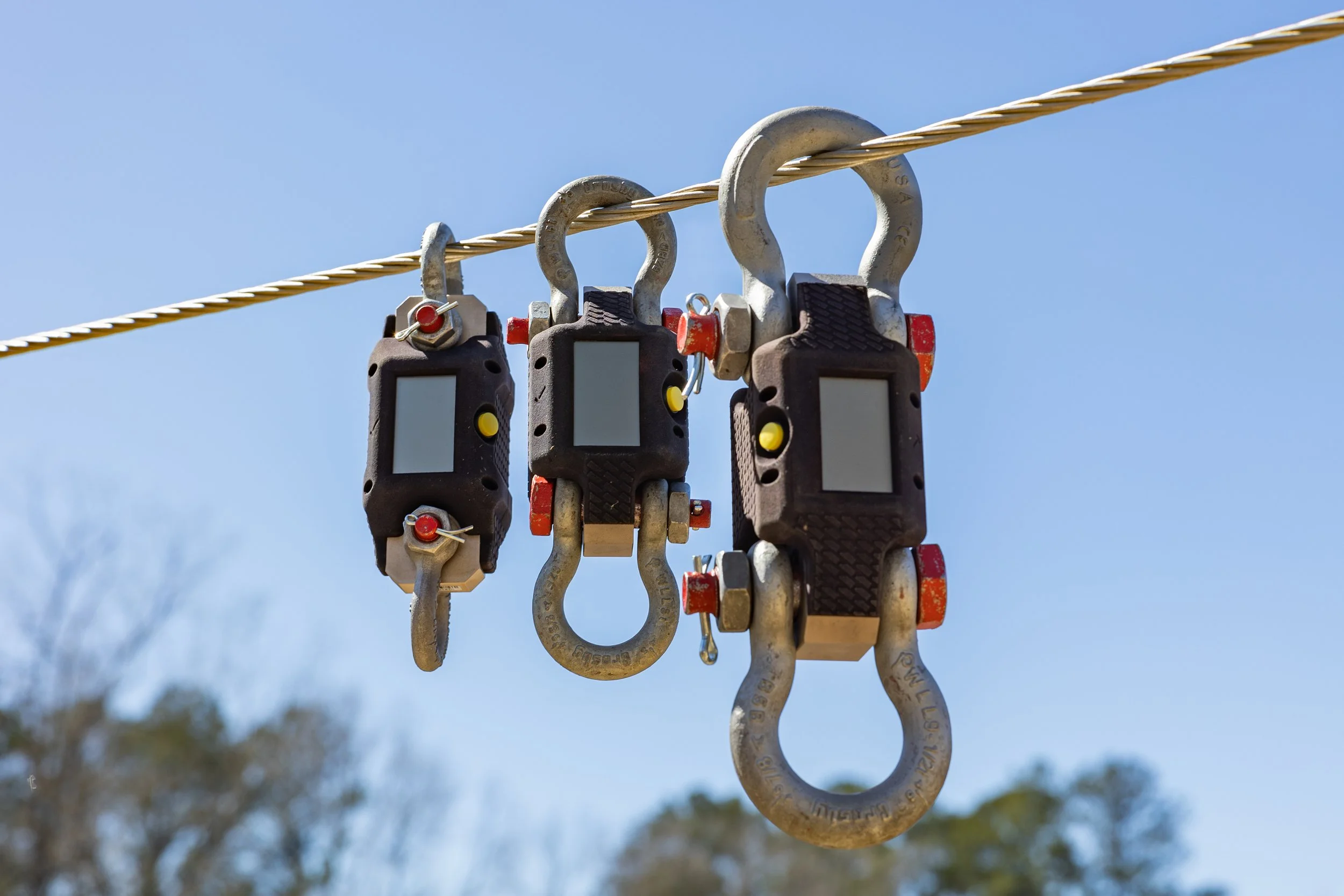
The 5k, 10k and 20k Power Line Dynamometers
During construction, tension accuracy is everything. Power line dynamometers are used while stringing and sagging conductors to directly measure the mechanical tension being applied to the line.
By providing real-time tension feedback, dynamometers allow crews to:
Verify that conductors are being tensioned to design specifications
Adjust for span geometry, structure height, and loading assumptions
Prevent over-tensioning that can damage conductors or structures
Ensure sag will fall within required clearance limits once the line is energized
When used correctly, our 5k, 10k, and 20k Dynamometers remove guesswork from the stringing process and help ensure the line is built right the first time. During pulling, a dynamometer is placed in-line with the conductor to monitor real-time load and prevent overstressing. Crews must simply input their company’s sag charts into the Vulcan Line Tools app, select the wire type, span length, and ambient temperature, and then start the pulling process.
The WaveTimer: Verifying Tension During Maintenance and Existing-Line Work
Once a line is built, tension is no longer directly observable, but it still governs sag, clearances, and long-term performance. That’s where WaveTimer comes in.

The WaveTimer measures a wave during a conductor “jerk test.”
The WaveTimer reduces uncertainty during maintenance and verification by directly measuring conductor response instead of relying on assumptions or indirect calculations. By analyzing how a conductor behaves during a standard “jerk test”—in which a lineman physically jerks a conductor, creating a measurable wave—the WaveTimer produces accurate, repeatable tension data that inherently reflects real-world conditions.
Crews can input their company’s sag charts into the Vulcan Line Tools app, select the wire type and span length, attach the device to the conductor, and perform the test. An onboard infrared sensor also captures the conductor’s exact temperature, removing one of the most common sources of error in sag and tension evaluation.
Built for the Full Lifecycle of Overhead Lines
Together, dynamometers and the WaveTimer address sag and tension from both sides:
The 5k, 10k, and 20k Dynamometers ensure correct tension during construction.
The WaveTimer verifies actual tension during maintenance and existing-line assessments.
The result is faster verification, fewer assumptions, and better-informed decisions across both transmission and distribution systems.